|
Securitex Wireless Key
Pad system
|
|
Prastel True Wireless Keypad. Design for Glass Door and Outdoor application |
|
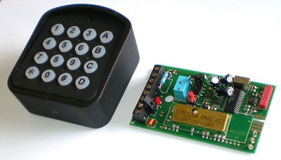
Securitex WDPA-Radiokey
Securitex WDPA-Radiokey was designed for access control
into secured facilities where installation of the normal Access Control keypad
is not possible. This could be due to the location where the keypad is to be
installed is a glass panel or special material which does not allow normal
keypad to be installed. Furthermore laying cable from keypad to the access
control and locking system is not possible like on marble, granite or even
metal clad wall etc.
With the
WDPA - Radiokey the keypad can be secured on to this
surface using special adhesive and the secured code transmitted to the Wireless
receiver (MR1E) integrated to the access control system to release the
electromagnetic lock.
Area of used
The WDPA - Radiokey can be use indoor and outdoor area. This keypad is
very suitable to be install on Boat, Caravan, Garages
Door. Warehouse roller shutter, Automatic Barrier system.
Automatic Gate, Office Glass Door and even as a home automation keyboard to
activate lights, fan, air-condition etc, as for industries can be use to start
stop machine like pumps, compressors etc. The application is limitless.
DESCRIPTION
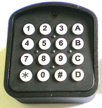
RADIOKEYB
is a numeric battery-powered
keyboard for the radio transmission of fixed-length, 5-digit codes (which may
be addressed on channels A, B, C and D) to receivers of the Multipass
and Roll series.
2. APPLICATIONS
Can be used to enter and store
access codes for any restricted access device such as automatic doors and
gates, lights, and so on. The keyboard does not require laying
of cables and is also suitable for outdoor installation. The front panel is
secured by means of screws and the keyboard itself, with incorporated LED, is protected by a soft-touch semitransparent plastic
cover. An appropriate compartment is provided for fitting in the battery.
Note: Features tamper-proof case and electronics.
Access to the electronics does not permit to activate the command.
3. TECHNICAL FEATURES
Transmission frequency 433.92 MHz
Duration of transmission about 1 sec
Operating range 40 meters to
70 meters
Type of code Multipass
Signaling devices Rear-illuminated
LED and buzzer
No. Of channels 4, can be
selected from the keyboard
Dimensions and weight 73
x 80 x 33 mm – 160 grams
Power supply 9V alkaline battery
Insulation Class IP 54
Power
consumption Nil
when not operating, 5mA for keyboard operations, 30mA for transmission
4. MOUNTING INSTRUCTIONS
Open the case and secure the bottom
to the support. Link up the battery and re-close (see fig. 2 and 3). The system
is now ready to operate.
Note: In case of outdoor
installation, it is recommended that the seals and washers provided be employed
in order to prevent water infiltration (see Figure 1).
5. OPERATION
Once the system has been powered,
the codes can be programmed proceeding as follows:
a)
Press the programming key on the
receiver to access the learning mode.
b)
Digit in the code and select one of
the four channels (A, B, C or D) by pressing the corresponding key. Exit from the learning mode by
pressing the appropriate key on the receiver or wait for 10 seconds for the
system to automatically exit from the learning mode.
5.1. ENTERING NEW CODES
The number of codes which may be
stored depends on the receiver memory capacity (Multipass
RPA function).
a)
Digit in a code already stored in
the memory of the receiver and press key # (Example: 12345 #).
b)
Enter a new code and select one of
the four channels by pressing the appropriate key (Example: 67890 A).
c)
Repeat step “b” above within
10 seconds to enter other new codes
d)
After 10 seconds of a code not being
entered, the system automatically exists from the programming mode and becomes
operative again.
6. NOTES
Pressing of any key set off the buzzer
and light up the LEDs. After transmission has been
made or upon the * key being pressed, the system returns to stand-by. Pressing
of the # key permits to program and enter new codes via radio commands (Multipass RPA function). The keyboard is provided with a
battery charge indicator which sets off both an intermittent warning light and
the buzzer when the battery is flat.
Can be employ in conjunction with
all 433 MHz Multipass and Multipass
Roll receivers.
MR1E Receiver operation manual
1. GENERAL INFORMATION
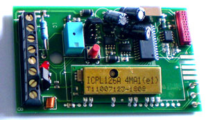
The receiver integrates the
functions of receiver and decoder of standard and Rolling Code codes. It memory
is capable of memorizing up to 200 different codes, both standard and rolling,
generated by transmitters of the MULTIPASS family.
2. ROLLING CODIFICATION
The purpose of this codification is
to prevent the possibility of violation of the code by capture and
retransmission. Rolling code involves the transmission of a batch of bits
consisting of a constant part, different for each transmitter, the channel bits
related to the transmitter switch activated plus a part that varies with each
transmission in a pseudo-random manner (rolling code) in accordance with a
proprietary Prastel algorithm. Configuration of these
bits varies unpredictably between two consecutive transmissions. The receiver,
by self-learning, memorizes the constant part of the code of each transmitter
plus the appropriate rolling code and updates the latter at each transmission.
The transmitter is recognized only if it sends a rolling code corresponding to
the 255 configurations subsequent to the last recognized transmission.
Nevertheless it allows realignment and recognition of a previously memorized
transmitter that has overrun the permitted interval (e.g. due to an excess of
unrecognized transmissions or on replacement of power supply batteries) by
pressing and releasing the transmitter learning button; in this way the
correctness of the code is analyzed, maintaining the advantages of the variable
codification. RPA Function (Transmitter remote self-learning
command)
3. MAIN TECHNICAL FEATURES
Power supply 12 - 24 VAC/DC
Average Work/Rest consumption 22 mA / 40
mA
Reception frequency 433.920 MHz
Number of codes capacity 200 (MR1E)
Number of channel 1
Types of output Mono-stable (Momentary) or bi-stable (Latch) Output Relay
Contact capacity 0,5 A @ 24 VAC/DC
Signals Red led
Working temperature -20/+55 °C
Storage temperature -40/+85 °C
Size / Weight 100 x 55
x 22 mm 70g
4. SELECTION OF SUPPLY VOLTAGE
The receiver can be supplied through
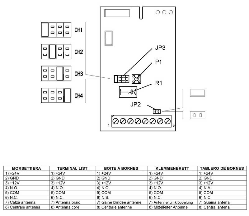
terminals 1 and 3 at 24 V or 12 VAC/DC.
5. CODE PROGRAMMING AND CANCELLATION
Operations of inserting a new code
into the memory and canceling the whole list of codes can be carried out using
the same button P1 on the receiver.
Programming
• Power up the receiver correctly.
• Press button P1: the red led
lights up indicating that programming is in progress.
• Carry out a transmission pressing
any transmitter button.
• The code is inserted into the
memory. The LED flashes during insertion. At the end the led returns to the
non-flashing state, indicating that a new code may be inserted.
• Memorize all the transmitters by
carrying out a transmission with each one.
• At the end of the operation press
button P1 again to exit from the procedure. The led goes out. Exit from the programmed
comes about automatically in any case 10 seconds after the last memorization.
• The codes remain in the memory
even if the power supply is cut.
Total cancellation of codes
• Hold button P1 pressed until the
red led starts flashing.
• Press button P1 again within 6
seconds to confirm cancellation. Confirmation is indicated by the led flashing
with greater frequency.
6. CHANNEL ADDRESS
The receiver’s output relay can be
activated by only one of the four channels available, after selecting the
channel required by means of the receiver’s JP3 jumpers (Fig. 1), of a
transmitter of the MULTIPASS family operating on a frequency of 433.920 Mhz.
7. SELECTION OF TYPE OF OUTPUT RELAY
The receiver’s on-board relay may be
of a monostable or bistable
type depending on how the JP2 jumpers are configured (jumper closed: monostable; jumper open: bistable).
SAFETY WARNINGS
These warnings are an integral and
essential part of the product and must be delivered to the user. Read them
carefully: they provide important installation, operating and maintenance
instructions. Keep this form and give it to any persons who may use the system
in the future. Incorrect installation or improper use of the product may cause
serious danger.
INSTALLATION INSTRUCTIONS
• Installation must be performed by
a qualified professional and must observe all local, state, national and
European regulations.
• Before starting installation, make
sure that the product is in perfect condition. • Laying, electrical connections and
adjustments must be done to “Industry Standards”.
• Packing materials (cardboard,
plastic, polystyrene, etc.) are potentially dangerous. They must be disposed of
properly and kept out of the reach of children
• Do not install the product in an
explosive environment or in an area disturbed by electromagnetic fields.
• The presence of gas or inflammable
fumes is a serious safety hazard.
• Provide an over voltage
protection, mains/knife switch and/or differential on the power network that is
suitable for the product and conforming to current standards.
• The manufacturer declines any and
all liability if any incompatible devices and/or components are installed that
compromise the integrity, safety and operation of the product.
• Only original spares must be used
for repair or replacement of parts.
• The installer must supply all
information regarding the operation, maintenance, and use of individual
components and of the system as a whole.
MAINTENANCE
• To guarantee the efficiency of the
product, it is essential that qualified professionals perform maintenance at
the times and intervals required by the installer, by the manufacturer and by
current law.
• All installation, maintenance,
repair and cleaning operations must be documented. The user must store all such
documentation and make it available to competent personnel.
WARNING FOR THE USER
• Carefully read the enclosed
instructions and documentation.
• This product must be used for its
intended purpose only. Any other use is improper and therefore dangerous. The
information contained herein and in the enclosed documentation may be changed
without notice and are in fact provided in an
approximate manner for application of the product. Prastel
S.p.A. declines any and all liability in this regard.
• Keep this product, devices,
documentation and all other items out of the reach of children.
• In case of maintenance, cleaning, breakdown or malfunction of this
product, turn off the unit and DO NOT try to repair it yourself. Call a
qualified professional only. Disregard of this instruction may cause extremely
dangerous situations.
Download product brochure and operation manual
Marketed
and distributed by
Securitex Electronic
Systems Engineering
Block 9010 Tampines St 93 #04-145 Tampines
Industrial Park A Singapore 528844 Tel: +65 67852171 Fax:
+65 65850107
http://www.securitex.com.sg |


